
Festo CMMT-ST Servo Drive — EtherCAT Integration with Omron Sysmac Studio
A practical guide to configuring the CMMT-ST in Festo Automation Suite and commissioning it as an EtherCAT axis in Sysmac Studio.
Introduction
There are plenty of articles and YouTube videos out there covering how to set up the Festo CMMT-ST drive in isolation. However, most of them stop short of showing the full picture — particularly when it comes to integrating the drive into a third-party PLC environment over EtherCAT. That gap is exactly what this article addresses.
In this guide, we will walk through the complete process: configuring the CMMT-ST in Festo Automation Suite, exporting the necessary EtherCAT device description files, importing them into Omron Sysmac Studio, and commissioning the drive as a motion axis. There are a few details along the way that are easy to miss, and I will highlight each one clearly.
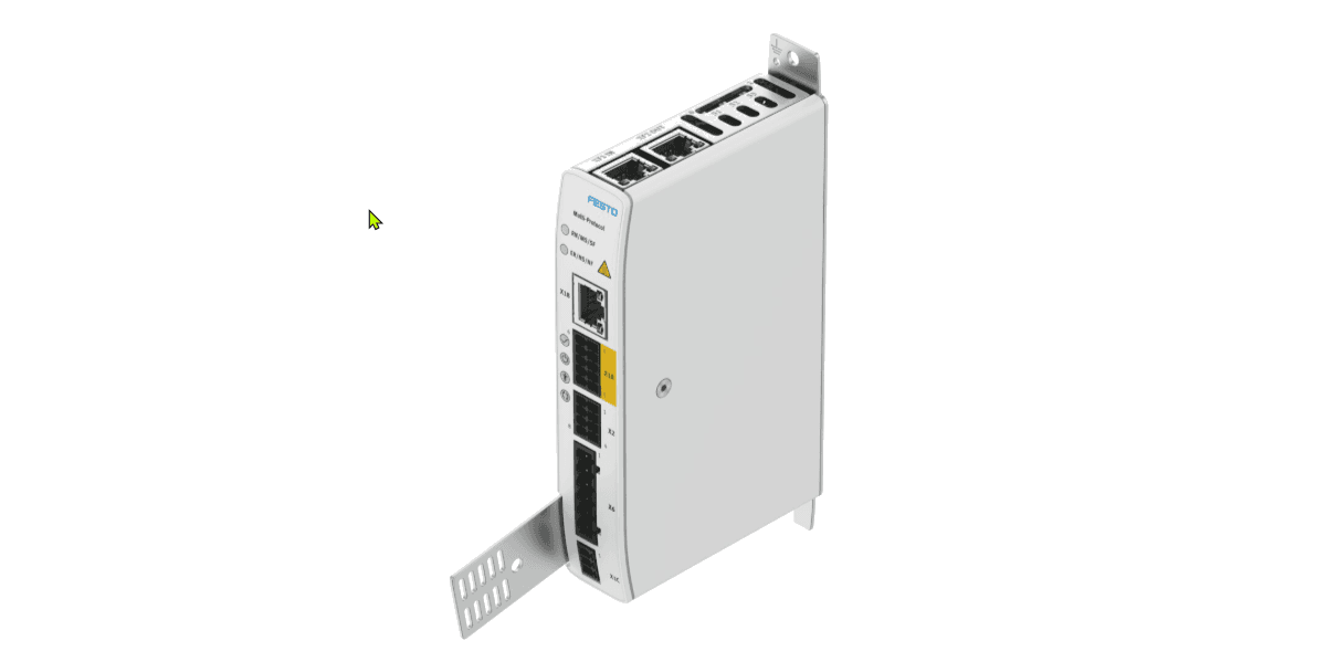
For this setup we are using a CMMT-ST-C8-1C-MP-S0 servo drive paired with an ERMS-25-ST-E rotary stage. The communication bus is EtherCAT.

Hardware Used in This Guide
| Component | Part Number / Description |
|---|---|
| Servo Drive | Festo CMMT-ST-C8-1C-MP-S0 |
| Rotary Stage | ERMS-25-ST-E |
| PLC Platform | Omron Sysmac (NJ/NX series) |
| Fieldbus | EtherCAT |
| Drive Software | Festo Automation Suite |
| PLC Software | Sysmac Studio |
Part 1 — Festo Automation Suite
Initial drive configuration before touching the PLC side
Before integrating the CMMT-ST into Sysmac Studio, it needs to be configured on the Festo side first. Festo Automation Suite is the dedicated commissioning and configuration tool for the CMMT range. If you do not already have it installed, download it from the Festo website — it is free.
A big thank you to soup01.com — this website was a helpful reference during the initial setup and pointed me in the right direction on several configuration steps.
Inside Festo Automation Suite, connect to the drive over USB or Ethernet and work through the Drive Configuration wizard. Select your servo drive model, motor, axis, and mounting hardware. The screenshot below shows a correctly configured system with the CMMT-ST-C8-1C-MP-S0 drive and ERMS-25-ST-E rotary stage.

Pay close attention to the Factor Group settings under the unit scaling section. These values define the decimal precision used for position, velocity, acceleration, and jerk commands. As you can see in the screenshot below, Position is set to −6 — meaning 6 decimal places.

These values must be replicated exactly in Sysmac Studio during axis unit configuration. We will cover this in detail in Part 3. Once the drive is configured and you can jog the axis successfully from within Festo Automation Suite, you are ready to move on.
Part 2 — Sysmac Studio Network Configuration
Adding the CMMT-ST to the EtherCAT network
Download the EtherCAT Device Description Files
Sysmac Studio needs an EtherCAT XML device description file (ESI file) to recognise the CMMT-ST on the network. Download these directly from the Festo support portal:
Festo CMMT-ST Support Portal — ESI Files →
Download all available ESI file versions, not just the latest. Drives in the field may be running older firmware, and the ESI file version must match the firmware on your drive. Having all versions saves time if the network scan fails to identify the device.
Install the ESI Files in Sysmac Studio
With the downloaded XML files ready, open Sysmac Studio. In the EtherCAT network view, right-click on the Master node and select Display ESI Library to open the device library where you can install the new files.

Only one instance of Sysmac Studio can be open when installing device description files. Close all other projects before attempting the import — otherwise the installation will fail silently or produce an error.
Scan the EtherCAT Network
With the drive powered up and the EtherCAT cable connected to the PLC, click Compare and Merge with Actual Network Configuration. Sysmac Studio will scan the network and show you a side-by-side comparison of the configured and actual devices.

If the drive does not appear automatically, you can also drag and drop the CMMT-ST from the ESI device library on the right-hand panel. Select the correct revision that matches your drive firmware.

If the scan still fails to find the drive, check:
- •The ESI file version matches the firmware on the drive
- •The EtherCAT cable is connected to the correct port on the drive
- •The drive is fully powered (both 24 V control supply and DC bus)
Set the Node Address and Download to PLC
Once the drive appears in the network tree, assign it a node address. Then download the configuration to the PLC.
After the download completes, check the EtherCAT network view. Every device in the tree should show a play symbol (▶). This confirms the device is in operational state, communication is active, and no errors are detected. If any device shows a different symbol, check the drive status LEDs and the Sysmac Studio diagnostics panel.
Part 3 — Adding the Motion Axis
Configuring the servo axis in Sysmac Studio Motion Control Setup
Create a Single-Axis Position Control
In the Sysmac Studio project tree, navigate to Motion Control Setup → Axes. Right-click and select Add Axis → Single Axis Position Control. This creates a new axis object that you will link to the CMMT-ST drive.
Map the PDO Variables
With the axis created, open the axis settings and map it to the CMMT-ST EtherCAT node. When you first open the PDO mapping section, some process data objects may not be automatically assigned — Sysmac Studio will not always complete this on its own.

Once the PDOs are mapped in the axis settings, you also need to go to the I/O Map and create variable tags for the drive. This is where Sysmac Studio links the physical EtherCAT process data to Global Variables in your PLC program — without these tags, you will not be able to read or write the drive data from your code.

Check every PDO entry manually. Unmapped PDOs are one of the most common reasons the axis fails to go operational. At minimum you need: Control Word, Status Word, Target Position, Actual Position, and Target Velocity all correctly mapped and tagged.
Configure Unit Scaling — Critical Step
This is the step most guides skip, and the one most likely to cause confusion. The unit scaling in Sysmac Studio must match exactly the Factor Group values you set in Festo Automation Suite.
In the axis Unit Conversion Settings, set Command Pulse Count per Motor Rotation to 1,000,000 and Work Travel Distance per Motor Rotation to 1 degree/rev — matching the default settings from Festo Automation Suite.

How the scaling works:
If these values do not match between the two tools, the axis will move to incorrect positions or generate position error faults.
Set the Encoder Mode to Absolute
In the Position Count Settings, set the Encoder type to Absolute encoder. This ensures the drive retains its position reference across power cycles, eliminating the need for a homing routine on every startup.

Configuration is complete. Download to the PLC, bring the EtherCAT network online, and verify the axis status shows Standstill with no active faults before commanding any motion.
Running the Axis
With the axis configured and the EtherCAT network operational, you can implement motion control logic using the PLCopen Motion Control function blocks — the standard library supported across all Omron Sysmac platforms.
You can also write custom function blocks for application-specific sequences — homing routines, index moves, or coordinated multi-axis motion.
Summary
- ✔Configure the CMMT-ST in Festo Automation Suite first — verify the axis moves before touching the PLC
- ✔Note your Factor Group values (Position −6) — they must match Sysmac Studio unit settings
- ✔Download all ESI file versions from Festo — the version must match the firmware on your drive
- ✔Only one Sysmac Studio instance can be open when installing ESI device description files
- ✔Always verify the PDO mapping manually — automatic mapping is often incomplete
- ✔Unit scaling must match exactly between Festo Automation Suite and Sysmac Studio
- ✔Set encoder type to Absolute to retain position across power cycles
- ✔Confirm green ▶ symbols on all EtherCAT devices before attempting motion
This article is an independent technical guide for informational purposes. All product names and trademarks are the property of their respective owners (Festo SE & Co. KG and Omron Corporation). Always verify configuration parameters against the current official documentation for your specific hardware and firmware versions.

Comments
No comments yet. Be the first!